Networking Fundamentals
Overview
Many technical people have only a rudimentary grasp of networking fundamentals. How does subnetting work? How are routing decisions made? What does the MAC address actually do? While most are familiar with these things, they lack a real grasp of what they do and how they interact. Hopefully this article should shore up your understanding of the entire
TCP/IP suite.
Key terms
Before we dig into the details, it's important that we review and define a few terms that you may not have previously learned.
-
node (n.) - Any single device on a network. A node can be a computer, a network-enabled printer, a router, a managed switch, or something else.
-
bit bucket (n.) - That place where discarded bits are thrown.
-
copper (n.) - For purposes of this document, we are only talking about Cat-5 and similar networking cables that send a signal down pairs of copper wires. Many other methods of transmitting data are possible, including fiber-optics, radio waves, even pigeons (for very low bandwidth purposes only of course). Cat-5 and its derivatives are
the most common physical media for transmitting data however, so canonically, copper means Cat-5 and similar cables. -
TTL (n.) Time to Live. In networking, this often isn't in seconds, but rather in nodes to traverse before dying.
-
canonical (adj.) - The usual way.
Binary arithmetic
In later portions of this document, we discuss binary numbers a good deal, so it's important to have a strong grasp on them before proceeding. As you probably already know, computers deal exclusively with 1s and 0s. There is no number 2 in a computer, nor a number 3. Every number, every letter, every pixel, every process is expressed as a string of seemingly random 1s and 0s. How we determine what a particular string of 1s and 0s means is what this section is all about.
To demonstrate, look at your hand - five fingers. You might think it's possible to count up to only five on your hand, but if you think of your fingers as individual bits that can be turned on and off (as a computer would), you'll realize you can count all the way to
- If a finger is down, that finger is a 0. If it is up it becomes a 1.
Decimal      Binary
0            00000
1            00001
2            00010
3            00011
4            00100
5            00101
6            00110
7            00111
8            01000
9            01001
10           01010
11           01011
12           01100
13           01101
14           01110
15           01111
16           10000
..           .....
31           11111
Binary is a base 2 system, and with each power of 2, the 1 shifts to the left a single bit. I call this the Staircase of Two.
Power        Decimal        Binary
0            1              00000001
1            2              00000010
2            4              00000100
3            8              00001000
4            16             00010000
5            32             00100000
6            64             01000000
7            128            10000000
We could go further out to the nth power, but this is as far as we need to go for most practical purposes. Compare the above base 2 table to the more familiar base 10 table.
Power        Decimal        Base Ten
0            1              00000001
1            10             00000010
2            100            00000100
..           ...            ........
7            10000000       10000000
Here you can easily see the "ones place", the "tens place", the "hundreds place" and so on. In binary, we have the same thing, except that we have a "ones place", a "twos place", a "fours place", an "eights place" and so on.
Looking back at the binary table, you can see that by adding these together, we can quickly create any number we choose. Let's assume we want to find the binary value of 47.
To do this easily, we simply find the largest power of two that's smaller than 47, and put a 1 in that power's place. Then we subtract that value, and continue on down the line. So what's the largest power of 2 that's not larger than 47? 32 is smaller, and 64 and above are too big, so we know that the first 1 in our binary number will be in the sixth spot from the right.
Note: Remember that the first place is the power of zero. Computers start counting at zero, and you should too.
47 - 32 = 15
Our binary number looks something like this now.
001?????
What's the largest power of 2 that's not larger than 15? Well, the next place in binary is 16, but that's too large, so we'll put a 0 there.
0010????
8 works! So there will be a 1 in the fourth place from the right.
15 - 8 = 7

00101???

7 - 4 = 3

001011??

3 - 2 = 1

0010111?

1 - 1 = 0

00101111
As you can see, the decimal (base 10) 47 is 00101111 in binary (base 2).
Converting from binary to decimal is even easier. To find the value of 11011001, we simply find the decimal value for each 1 and ignore the values for each 0.
11011001 = 128 + 64 + 16 + 8 + 1 = 201
An alternative way to look at this is to say that 11011001 has one 128, one 64, one 16, and so on.
11011001 = (1 * 128) + (1 * 64) + (1 * 16) + (1 * 8) + (1 * 1)
You can also look at the decimal number the very same way.
201 = (2 * 100) + (0 * 10) + (1 * 1)
Now that you know binary, not only can you count to 31 on one hand, but you can also understand concepts like IP addressing and subnetting.
Five layers at a glance
The TCP/IP suite makes use of five different layers to get its job done. There are a couple of other layers that come into play, but you will rarely run into them unless you are doing exotic things like multi-casting. You can think of the layers in much the same way that you think of a stack of blocks. At the bottom is the physical layer, and at the top is the application layer. Things start at the top and slowly work their way down the layers to create a network frame. Each of these layers will be briefly explained now; we will go into more depth in later sections.
-
Physical layer - The lowermost layer in our stack of blocks. This layer consists of basically any physical part of your network. "Physical" is a bit of a misnomer though, as it includes non-physical transmission media such as light or radio signals. Basically anything that is capable of actually transmitting data is part of the physical layer. This
includes network cards, copper wires, fiber-optic cable, radio waves, and even infrared light. The physical layer turns the digital packet into some form of analog signal that can be transmitted to another node on the network. -
Data-link layer - The first layer of the TCP/IP stack that actually crafts part of the packet. This layer is also responsible for determining what machine will receive a packet on any given network-layer subnet.
-
Network layer - Responsible for addressing hosts that may or may not be on your particular LAN. It is the only protocol that understands routing and can address packets to machines not on your LAN.
-
Transport layer - Responsible for communicating between the network layer and the application layer. It is responsible for determining what application a given packet will reach. It is also the only layer that can guarantee data transmission.
-
Application layer - Responsible for formatting the data that will be transmitted to a remote host. It includes most of the higher order protocols you may be familiar with such as DHCP, DNS, and HTTP.
Physical layer
As we discussed, the physical layer is responsible for transforming digital signals. How this happens depends on the transmission media of course. Fiber-optic cables send light signals of course. Copper wires transmit data in voltage fluctuations. Radio communications send the signal along a certain radio frequency. We'll only discuss the
most common, copper, below.
802.3 cabling
802.3 is the Institute of Electrical and Electronics Engineers (IEEE) spec that defines ethernet. The most common transmission media for Internet traffic is copper cable. Ethernet has reached speeds of 10, 100, 1000, and even 10000 megabits per second (Mbps). Cabling has changed over time from incredibly thick coax cable to thin twisted pair copper
which is prevalent today. A typical cable consists for four pairs of copper with each pair twisted about itself. This twists generates a small electromagnetic shield around the cable that helps prevent interference and increases the amount of data that can be sent through the wire in a given period of time.
A typical Cat5e cable is terminated in an RJ-45 connecter that looks like an oversized phone jack. Inside the cable you will find 4 different colored pairs of wire. In 10/100 Mbps ethernet, only pairs 1 and 2 transmit data. Pairs 3 and 4 are left vacant but can be used to power a remote node using Power over Ethernet (PoE).
Pair 1: Orange / Orange-white
Pair 2: Green / Green-white
Pair 3: Blue / Blue-white
Pair 4: Brown / Brown-white
Unfortunately, how these pairs are wired is a little counter-intuitive and depends on whether you are using an intermediate hub or switch, or if you are connecting two Network Interface Cards (NICs) directly. The typical way of terminating these cables is known as 568B. A 568B termination looks a bit like this.
                   RJ-45 Terminator
             ===========================
             ||  Orange-white --------||
             ||  Orange       --------||
=============||  Green-white  --------||
 Cat5e Cable ||  Blue         --------||
=============||  Blue-white   --------||
             ||  Green        --------||
             ||  Brown-white  --------||
             ||  Brown        --------||
             ===========================
If both ends of the cable are terminated in this fashion, then the cable is called a patch cable. However, if only one end is terminated in the following fashion, then the cable is known as a crossover cable and can connect two computers without an intervening switch or hub.
                   RJ-45 Terminator
             ===========================
             ||  Green-white  --------||
             ||  Green        --------||
=============||  Orange-white --------||
 Cat5e Cable ||  Brown        --------||
=============||  Brown-white  --------||
             ||  Orange       --------||
             ||  Blue-white   --------||
             ||  Blue         --------||
             ===========================
You might be wondering why this isn't necessary if the cable is plugged into a hub or switch. The reason is that certain pairs of wire are for sending data and others are for receiving data. A hub or switch has these reversed. Here's a standard cable for a 0/100Mb ethernet connection with the pairs marked according to whether they are to transmit or receive data. (100Mb Ethernet only uses two wire pairs. Gigabit Ethernet uses all 4.) Each pair has a positive cable and a ground cable.
        NIC                  Hub or Switch
===================       =================
||  Output  -----|| 1   1 ||---- Input   ||
||  Output  -----|| 2   2 ||---- Input   ||
||  Input   -----|| 3   3 ||---- Output  ||
||  Unused  -----|| 4   4 ||---- Unused  ||
||  Unused  -----|| 5   5 ||---- Unused  ||
||  Input   -----|| 6   6 ||---- Output  ||
||  Unused  -----|| 7   7 ||---- Unused  ||
||  Unused  -----|| 8   8 ||---- Unused  ||
===================       =================
Here, you would want to use a patch cable, as the NIC's Output lines up with the hub's input and vice-versa. A crossover cable simply handles this for you if the two interface ports have the same pin setup. Consider this example:
       NIC 1                     NIC 2
===================       =================
||  Output  -----|| 1   1 ||---- Output  ||
||  Output  -----|| 2   2 ||---- Output  ||
||  Input   -----|| 3   3 ||---- Input   ||
||  Unused  -----|| 4   4 ||---- Unused  ||
||  Unused  -----|| 5   5 ||---- Unused  ||
||  Input   -----|| 6   6 ||---- Input   ||
||  Unused  -----|| 7   7 ||---- Unused  ||
||  Unused  -----|| 8   8 ||---- Unused  ||
===================       =================
If we were to connect a patch cable between these two NICs, no data could flow through because each NIC would attempt to transmit and receive on the same pairs. But by connecting a cross-over cable, you can see that everything flows smoothly.
       NIC 1                     NIC 2
===================       =================
||  Output  -----|| 1   3 ||---- Output  ||
||  Output  -----|| 2   6 ||---- Output  ||
||  Input   -----|| 3   1 ||---- Input   ||
||  Unused  -----|| 4   4 ||---- Unused  ||
||  Unused  -----|| 5   5 ||---- Unused  ||
||  Input   -----|| 6   2 ||---- Input   ||
||  Unused  -----|| 7   7 ||---- Unused  ||
||  Unused  -----|| 8   8 ||---- Unused  ||
===================       =================
Voltage transmission
So now that we know what each cable is for, and how to wire up a cable, how does a NIC actually transmit data? To understand this, we have to answer the age old question: "What is digital anyway?" A Google search will return all kinds of definitions for "digital", but none of them are very clear unless you already understand "digital". Here is my simpler definition: "Digital" is just a way of interpreting an analog signal.
Your copper cable always carries a voltage, and as this voltage changes, the remote NIC interprets this change as either a 1 or a 0. Let's assume your NIC is capable of producing voltages between 1 and 5 volts and that above 3 Volts is considered a "1" and below 3 Volts is considered a "0". Voltage always changes on a curve that resembles a sine wave.
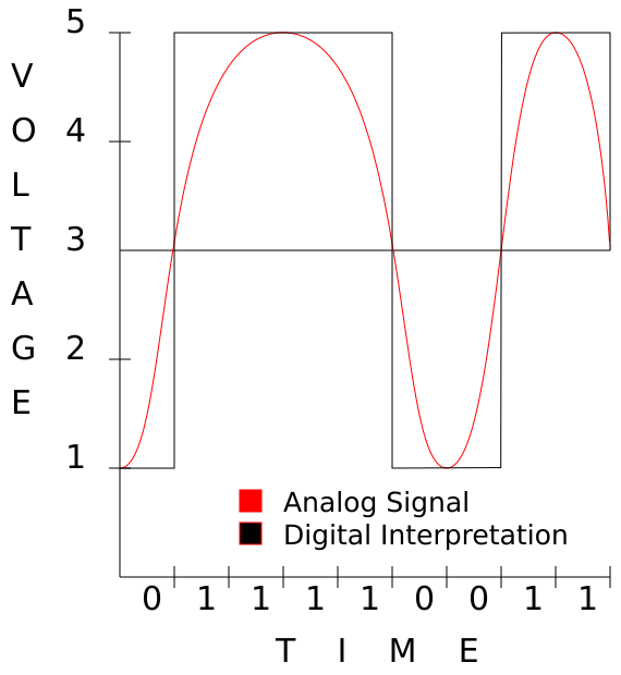
This should clearly show how changing voltage, even though the change is analog, can be interpreted as ones and zeros digitally.
Repeaters
A repeater is a simple device that takes a signal in and retransmits it. Repeaters are necessary to send data along particularly long cables because the signal tends to degrade. At distances longer than 100 meters yard, copper cables begin to experience large amounts of distortion and impedance. So if you wanted to ensure the integrity of a transmission between two nodes that were 200 meters apart, you would use two 100-meter-long cables and
connect them to a repeater in the middle.
Repeaters aren't a common networking tool. Typically, when data needs to be transmitted along long distances, we prefer to use technologies such as fiber-optic cables which have more reliable long-distance transmission capabilities.
Hubs
Hubs are devices with multiple ethernet ports that basically split a cable so that a single packet reaches multiple nodes. A hub's singular function is to accept signals on any of its interfaces and propagate those signals down all of its other ports. Basically, a hub is nothing more than a multi-port repeater. A hub enables one node to contact multiple other nodes.
Today, however, hubs have fallen out of favor due to the prevalence of switches for a variety of reasons. The main problem with a hub is that only one node may send data at a time, and each node is responsible for collision detection. Collisions occur when more than one node attempts to send data at a time. Most hubs are capable of disconnecting a
node that is producing more than its fair share of collisions, preventing a single misbehaving machine from bringing down the entire network, but this is still far from an ideal solution.
Hubs are considered "dumb" devices, because they replicate data unnecessarily. Only the single machine that a packet is destined for needs to receive the packet, but a hub has no way of knowing what that machine is or where it is located. Thus, a hub just "spams" each signal it receives to every machine it can reach.
Data-link layer
The Data-link layer is responsible for sending packets "somewhere", even if "somewhere" isn't their final destination. We will discuss only Ethernet (802.3) here as it is predominant, however, wireless Ethernet (802.11) is similar enough that most everything we will discuss here applies to it as well.
MAC addressing
Every NIC, every switch, every modem, and every device that connects to a network has a Media Access Control (MAC) address that is set by the device's manufacturer and is generally considered unchangeable. This address uniquely identifies a single device on a network segment, enabling us to address data for that particular device. In an ethernet
frame, we include two of these: a destination MAC address, and the source MAC address.
When you send a packet, the packet is tagged with your MAC address as the source MAC, and you will set the destination MAC to the address of the node you wish to reach, or to your router's MAC address if the final node isn't on your subnet. This will all make more sense when we look at the network layer.
Bridges
Bridges were designed as a way of limiting collisions on a network using hubs to connect many different machines by partitioning the network. A bridge is basically a dedicated computer with more than one NIC that sits between two or more hubs. A bridge works like a hub, but with one exception. A bridge has "brains" that can remember what machines are on either side of it. When it receives a packet, it consults its memory to see if the destination MAC is on the same interface as the source MAC. If so, it discards the packet. However, if they are on different interfaces, it propagates the packet only along the proper interface.
=======================                    =======================
|      Hub A          |--------------------|        Hub B        |
=======================                    =======================
    |           |                              |           |
    |           |                              |           |
==========  ==========                     ==========  ==========
| Node 1 |  | Node 2 |                     | Node 3 |  | Node 4 |
==========  ==========                     ==========  ==========
In this example, if Node 1 sends a packet to Node 2, the packet traverses both hubs, so nodes 2, 3, and 4 will all see the packet. Only node 2 will act on it, and the others will ignore it. Obviously, this is less efficient since every single node has to do collision detection for three other nodes.
=======================     ==========     =======================
|      Hub A          |-----| Bridge |-----|        Hub B        |
=======================     ==========     =======================
    |           |                              |           |
    |           |                              |           |
==========  ==========                     ==========  ==========
| Node 1 |  | Node 2 |                     | Node 3 |  | Node 4 |
==========  ==========                     ==========  ==========
In this example network, if Node 1 sends a packet to Node 2, both Node 2 and the bridge see the packet. Node 2 accepts the packet, and the bridge silently drops the packet to the bit bucket. Now suppose Node 1 sends a packet to Node 3. Node 2 and the bridge see the packet. Node 2 drops the packet in its bit bucket, but the bridge sends the packet to Hub B where both Node 3 and Node 4 see it. Node 3 acts on the packet and Node 4 ignores it. This is much more efficient because each node has to do collision detection for only two other devices (the other node on its hub, and the bridge). You can see how this improves things if you have dozens or hundreds of nodes on a hub network. Today however, bridges have lost their role as performance enhancers due to the prevalence of switches, and you'll soon find out exactly why. Bridges are primarily used today as specialized devices such as transparent firewalls or data filters, but we won't be discussing that in this article.
Switches
At first glance, switches are indistinguishable from hubs. They look identical, but the magic is all on the inside. Whereas hubs operate entirely on the physical layer, a switch steps up to the data-link layer and functions more like a bridge than a hub. If you recall from the earlier example, every node on a hub has to do collision detection and prevention with every other node on the hub and any other hubs that are directly attached to it. If a node is attached to a switch, however, the node has to avoid collisions with only the switch. How is this possible? Well, that's where the magic comes in.
Imagine that every single port on a hub was a bridge. This bridge would only send any given packet directly to the single machine the packet is destined to. This is exactly how a switch operates. By memorizing the MAC addresses of all devices attached to it, a switch is capable of looking at a packet's destination, and sending the packet to only the single port where the destination node is attached. This means that on a switch, a machine sees only packets that are intended for it. Not only does this prevent collisions, but it also increases overall throughput as multiple machines may send packets at the same time.
=================================================================
|                            Switch A                           |
=================================================================
  | 1 |      | 2 |      | 3 |      | 4 |      | 5 |      | 6 |
  =====      =====      =====      =====      =====      =====
    |          |          |          |          |          |
    |          |          |          |          |          |
========== ========== ========== ========== ========== ==========
| Node A | | Node B | | Node C | | Node D | | Node E | | Node F |
========== ========== ========== ========== ========== ==========
This is a typical 6-port switch with 6 nodes attached to it. Say that Node A wants to send a packet to Node B. The switch receives the packet on port 1, checks at its interface table, and determines that the packet is destined for Node B, which it knows is on port 2. The packet is sent out to port 2, and only port 2. Nodes C, D, E, and F never see the packet and in fact, will never even know it existed. Moreover, Node C can send Node D a packet at the same time without fear of collision, since the packets don't travel on the same physical link.
It's important to remember that switches are not security devices, but rather performance devices. It is possible to flood a switch's ARP table and make it either crash or convert to working as a hub depending on the make and model. You should never rely on a switch as a way of preventing disclosure of information.
Address Resolution Protocol
Address Resolution Protocol (ARP) is a protocol used to resolve hardware addresses from network addresses. Canonically, this means that if you know a node's IP Address, you use ARP to discover its MAC address. ARP packets are non-routable, so they tell you only the MAC addresses of nodes on your LAN. A typical ARP dialogue looks like this.
whippoorwill:  "Hey! Who out there is 172.30.16.19?"

nightingale: "Huh? Oh that's me! I'm 00:B0:D0:23:62:F2."
And now whippoorwill knows that 192.168.1.197 maps to 00:B0:D0:23:62:F2. That's really all there is to it. ARP is strictly an Ethernet protocol and once was used to resolve addresses in non-IP networks like Chaosnet. These days, everyone uses Internet Protocol. In IPv6, this functionality is handled by the similar Neighbor Discovery Protocol (RFC
4861).
Network layer
The network layer is responsible for determining the final destination of a packet and determining how to get there. Without this layer, no machine could address any other machine without knowing its MAC address, and those machines would have to be on connected hubs, bridges, and switches.
IP addressing
Simply put, an IP address is a 32-bit binary number. It's a string of 1s and 0s 32 digits long. For various reasons, we split that 32-bit number up into four 8-bit numbers. Let me use a common example.
192.168.1.100 is a common IP address on many private networks as it is one of the most easily remembered default IP addresses for a private LAN. What does the computer see when we send a packet to this address? To answer that question we need to know something about binary arithmetic. If you skipped the section on binary arithmetic, now may be a good time to go back and review it.
192.168.001.100 = 11000000.10101000.00000001.01100110
In reality, the dots don't exist. They are only there to help us work with four 8-bit numbers instead of 1 big 32-bit number. In reality, the computer just sees 11000000101010000000000101100110.
So now you know what an IP address is. Just like with the MAC address, every packet has a destination IP address and a source IP address.
Subnetting
Subnetting is properly called Classless Inter-Domain Routing and is formally described in the RFCs 1518 and 1519. Subnetting is a way of determining what IP addresses are on our network. Basically, it tells us what nodes we can talk to directly without communicating through a router of some sort. You've probably seen subnets like 255.255.255.0 or heard of them talked about as 192.168.1.0/24, but what do those numbers mean?
A subnet mask (or just a netmask for short) is a bitmask that tells the computer not to look at certain numbers. To understand this, we have to look at those numbers in binary.
255.255.255.0 = 11111111.11111111.11111111.00000000

192.168.1.100 = 11000000.10101000.00000001.01100110
In this example, a node (be that a computer, a managed switch, a router, or something else) can look at these two numbers see that all numbers that begin 192.168.1 are on the same subnet.
Another way of looking writing this is 192.168.1.100/24. The /n tells us how many bits are in the bitmask. In this case, 24.
/24           = 11111111.11111111.11111111.00000000

192.168.1.100 = 11000000.10101000.00000001.01100110
The following table should help you understand the basics.
Subnet             Bitmask      Value
===============    =======      ===================================
255.255.255.255    /32          11111111.11111111.11111111.11111111
255.255.255.254    /31          11111111.11111111.11111111.11111110
255.255.255.252    /30          11111111.11111111.11111111.11111100
255.255.255.248    /29          11111111.11111111.11111111.11111000
255.255.255.240    /28          11111111.11111111.11111111.11110000
255.255.255.224    /27          11111111.11111111.11111111.11100000
255.255.255.192    /26          11111111.11111111.11111111.11000000
255.255.255.128    /25          11111111.11111111.11111111.10000000
255.255.255.0      /24          11111111.11111111.11111111.00000000
255.255.254.0      /23          11111111.11111111.11111110.00000000
255.255.252.0      /22          11111111.11111111.11111100.00000000
255.255.248.0      /21          11111111.11111111.11111000.00000000
255.255.240.0      /20          11111111.11111111.11110000.00000000
255.255.0.0        /16          11111111.11111111.00000000.00000000
255.0.0.0          /8           11111111.00000000.00000000.00000000
0.0.0.0            /0           00000000.00000000.00000000.00000000
This is a table of the most common subnets you will run across from the smallest (/32, a single node) to the widest (/0, everything).
The number of address on a given subnet is easily found using the following formula:
max_addr = 2^(32 - bit_mask)
So, if your bitmask is /32:
max_addr = 2^(32 - 32) = 2^0 = 1
If it's /24:
max_addr = 2$(32 - 24) = 2^8 = 256
But what IP addresses are included in one of those subnets? It's easy to figure out that 192.168.1.0/24 means all addresses from 192.168.1.0 to 192.168.1.255, but what about some obscure ones like 172.16.25.208/29? To determine this, we'll have to simply count up from 0.
A /29 subnet has eight IP Addresses, meaning that there are exactly 32 /29 subnets inside a /24 subnet. Let me make another table.
Subnet             Min IP           Max IP
======             ======           ======
172.16.25.0/29     172.16.25.0      172.16.25.7
172.16.25.8/29     172.16.25.8      172.16.25.15
172.16.25.16/29    172.16.25.16     172.16.25.23
.....
172.16.25.208/29   172.16.25.208    172.16.25.215
An alternative way of looking at this is to split the subnets one at a time. Here we start with a known /24 and break it down into two /25s. Whichever /25 contains our IP address will be broken down into two /26s and so on until we reach the final /29.
Subnet             Min IP           Max IP
======             ======           ======
172.16.25.0/24     172.16.25.0      172.16.25.255
...
172.16.25.0/25     172.16.25.0      172.16.25.127
172.16.25.128/25   172.16.25.128    172.16.25.255
...
172.16.25.128/26   172.16.25.128    172.16.25.191
172.16.25.192/26   172.16.25.192    172.16.25.255
...
172.16.25.192/27   172.16.25.192    172.16.25.223
172.16.25.224/27   172.16.25.224    172.16.25.255
...
172.16.25.192/28   172.16.25.192    172.16.25.207
172.16.25.208/28   172.16.25.208    172.16.25.223
...
172.16.25.208/29   172.16.25.208    172.16.25.215
Simple, right? Well, it used to be even simpler when we only had three netmasks.
Years ago, there were only three subnets. These were sufficient at the time, because the Internet was mostly private, very small, and no one dreamed that so many people would eventually be on it. (Technically, there were other subnets, but they were restricted to specialty uses such as multi-cast. We will not discuss them further.)
Class   Network          Addresses
=====   =======          =========
A       255.0.0.0        16,777,216
B       255.255.0.0      65,536
C       255.255.255.0    256
If an organization needed 300 IP addresses, they were given 65,536. If they needed 100,000, they were given 16,777,216. Clearly this was very wasteful and created shortages. To address this, classless subnetting was invented, allowing organizations such as ISPs to get only as many IPs as they needed (or pretty close to it). If I need 300 IP addresses, I
don't need a /16. A /23 includes 512 IP Addresses, and that's more than enough without wasting the other 65,024. An even better solution would be to provide me with a /24 network (256 addresses) and a second /26 network (64 addresses) for a total of 320. This of course, would require a router to pass packets between the two different subnets.
Today, you'll still hear this terminology from time to time. People often refer to any /24 subnet as a Class C network for example.
Route determination
Subnetting tells us what IP addresses we should be able to communicate with without going through a router, but what about other IP addresses? Route determination enables us to send information in the form of packets to places that we've never seen.
Every computer has a routing table, though it looks different depending on your operating system. Here's what my routing table currently looks like on Slackware Linux 14.2. Other operating systems format their routing tables differently, but the functionality is the same.
whippoorwill:~# ip route show
default via 172.30.16.1 dev eth0  metric 202
127.0.0.0/8 dev lo  scope link
172.30.16.0/26 dev eth0  proto kernel  scope link  src 172.30.16.28 metric 202
This requires a little bit of explanation. When a packet is being transmitted outward, the kernel checks the packet's destination IP address against the first column of the routing table. This column lists networks and their subnets. The kernel always prefers the most specific match. Let's look at a few examples.
My computer (whippoorwill, 172.30.16.28) wishes to send a packet to another (nightingale, 172.30.16.19). It forms a packet and sets the destination IP address to 172.30.16.19. Then the kernel checks its routing table and finds two matches for this address.
default via 172.30.16.1 dev eth0  metric 202
172.30.16.0/26 dev eth0  proto kernel  scope link  src 172.30.16.28
metric 202
The default route is a catch-all that should always match. Essentially, it is the network 0.0.0.0/0 - the entire Internet. However, 172.30.16.0/26 also matches, and is a much smaller subnet, so the kernel chooses to use it instead as it is more specific. This specific example has a lot of information here, but for now there's really only two things we are interested in.
- Does the route include a
via IP_ADDRESSstatement? - What
dev INTERFACEstatement is included?
The first statement tells us if we need to use a router (or a gateway) and what that router's IP address is. In this case, no router is specified, so we know we are not using one. The second statement tells us that this packet should leave our eth0 interface in order to reach its destination.
Suppose whippoorwill wants to talk to Google, which it has learned has an IP address of 74.125.21.105.The kernel checks the routing table and determines that the only match is the catch-all.
default via 172.30.16.1 dev eth0 metric 202
This time, the packet will be sent out the eth0 interface with a local destination of the gateway 172.30.16.1.
It's important to note that no packet is transmitted to an IP address. IP addresses are merely used to determine the route that a packet must take to reach its eventual destination. Packets are instead transmitted to MAC addresses. This will all make sense later when we put everything together.
Internet Control Message Protocol
Internet Control Message Protocol (ICMP) is formally described in RFC 792.
ICMP is mostly used to transmit error messages between machines. For example, if a router can't find a node with which you're attempting to communicate, you may see an ICMP Destination Unreachable error message. ICMP is used to transmit the most basic of information between nodes, and is highly specialized to this task to the point that it
cannot carry arbitrary data in the way that TCP or UDP can (these will be discussed in a later section). Each ICMP packet is given a certain type that specifies its use. Certain types may have a (sometimes optional) data section that can carry some small amount of arbitrary data.
The most common intentional use of ICMP by a user is the ping program. ping generates an ICMP type 8 packet. Type 8 is known as the Echo Request. When a machine receives such a packet, it replies to it with an ICMP type 0 Echo Reply packet.
Another common way of using ICMP is the traceroute command. This works by generating UDP packets with very short Time To Live (TTL) values. If a router sees a packet with a TTL value of 0, it will send out an ICMP type 11 Time Exceeded packet. Since every router that handles a packet must decrement the TTL value by 1, this creates an easy method of seeing what routers (and how many) two nodes are communicating through.
By far the most common uses of ICMP packets however, are those you never see. ICMP sends error messages telling a sending node that no more bandwidth is available. It also tells the sending node to redirect a message to a different route. In short, ICMP is the often-unseen little janitor of the TCP/IP Suite that keeps everything clean and tidy and informs
everyone when the floor is wet and slippery.
Transport layer
The transport layer is responsible for communicating the wishes of the application layer with the network layer, and in some cases, is responsible for ensuring that data arrives at its destination. You might think of the transport layer as a postman. He accepts letters (data) from you, and passes them off to be routed to their final destination. If you have to be certain the letter arrives at its destination, you can send it certified mail and get reasonable confirmation that it was indeed delivered.
Transmission Control Protocol
Transmission Control Protocol (TCP) is formally described in RFC 793.
TCP is the most widely used protocol in the transport layer, and the only thing in the entire TCP/IP suite that guarantees delivery of packets by using some fairly ingenious techniques. To start, TCP marks every packet with a sequence identification number. In the event that some packets are received out of order, the receiving node can re-arrange them
correctly. Also, TCP requires an acknowledgement of receipt for every packet, so the sending node knows without doubt if a packet was received. Finally, TCP includes a rudimentary checksum to verify that the data sent has not been changed en route.
TCP is known as a connection oriented protocol, because it sends all data in the framework of an open connection, rather than simply firing the data off like every other protocol and hoping the destination node receives it.
Ports
Ports are a way of communicating with the application layer. TCP has 65,536 total ports. Every TCP packet has a source port and a destination port. When a TCP packet is received, the kernel looks at the port number (1 - 65,536) and determines what application to send the data to base on this information.
Flags
TCP makes use of a number of flag to specify the type of TCP packet in much the same way that ICMP does. Unlike ICMP, a TCP packet can have multiple flags set at the same time. In this document, we're only going to discuss the four most common.
- SYN - Synchronize and prepare for a connection.
- ACK - Acknowledge that a packet has been received (and which one)
- FIN - Finished sending data
- RST - Reset connection immediately
Connection initialization
The three-way handshake is used to initiate a TCP connection. It's responsible for ensuring that both end nodes are available and are ready for data to be transmitted.
Suppose that whippoorwill wants to get some files from nightingale on a TCP connection. First, whippoorwill sends a packet to nightingale telling him that robin is trying to initiate a TCP connection with a SYN packet. As soon as nightingale receives this packet, he knows that whippoorwill wants to talk to him and acknowledges it with a SYN-ACK packet.
Finally, when whippoorwill receives this packet, he replies with an ACK to nightingale. This packet is sometimes called the SYN-ACK-ACK packet, but it's really just an ACK packet. This informs both nodes that everything is ready to proceed. It looks similar to this:
whippoorwill to nightingale - SYN
nightingale to whippoorwill - SYN-ACK
whippoorwill to nightingale - ACK
At this point, they are ready to transmit information. whippoorwill can send TCP packets without any flags and nightingale will reply to each packet with an ACK so whippoorwill knows that the data was received. If, for whatever reason, whippoorwill doesn't see an ACK packet for some data it sent, it will resend that packet.
Connection termination
So now that we know how to initiate a TCP connection, how do we stop one? The answer is the four-way handshake.
To stop a TCP connection gracefully, both sides must agree that all data transmission has finished. When each node has completed all the transmission it intends to do, it will send a FIN packet. This is responded to by an ACK packet. After both nodes have sent FIN and ACK packets, the connection is over. The reason that both nodes must agree that a
transmission is over is simple. One node may no longer wish to send data, but the other still has lots to transmit. When one node has finished a connection, but the other hasn't, the connection is called half-open.
For example, suppose that whippoorwill has requested a rather large file. Once this file has begun transmission, whippoorwill decides that he no longer wishes to send anymore requests and gives nightingale a FIN packet. nightingale** returns an ACK packet, but continues to send that large file until that is complete before sending its
own FIN packet. Here we will begin with the three-way handshake, begin transmitting data, and end with a four-way handshake.
Sender             Receiver       Flags       Content
======             ========       =====       =======
(three-way handshake)
whippoorwill      nightingale     SYN
nightingale       whippoorwill    SYN-ACK
whippoorwill      nightingale     ACK
(begin data transmission)
whippoorwill      nightingale                 Give me BIG_FILE
nightingale       whippoorwill    ACK
nightingale       whippoorwill                BIG_FILE part 1
whippoorwill      nightingale     ACK
nightingale       whippoorwill                BIG_FILE part 2
whippoorwill      nightingale     ACK
nightingale       whippoorwill                BIG_FILE part 3
whippoorwill      nightingale     ACK
nightingale       whippoorwill                BIG_FILE part 4
whippoorwill      nightingale     ACK
(begin four-way handshake)
whippoorwill      nightingale     FIN
nightingale       whippoorwill    ACK
(half-open connection)
nightingale       whippoorwill                BIG_FILE part 5
whippoorwill      nightingale     ACK
nightingale       whippoorwill                BIG_FILE part 6
whippoorwill      nightingale     ACK
nightingale       whippoorwill                BIG_FILE part 7
whippoorwill      nightingale     ACK
nightingale       whippoorwill                BIG_FILE part 8
whippoorwill      nightingale     ACK
(complete four-way handshake)
nightingale       whippoorwill    FIN
whippoorwill      nightingale     ACK
(connection torn down)
There is one other way to tear down a TCP connection, and that is the RST packet. When one node sends the other node an RST packet, everything is over. Both nodes immediately cease transmitting data and close the connection.
User Datagram Protocol
User Datagram Protocol (UDP) is formally described in RFC 768.
UDP communicates between the network layer and the application layer. At first glance, it looks a lot like TCP, but UDP can't work on connections. Rather, UDP simply "fires and forgets". This is actually preferred for many forms of transmission. Since UDP doesn't clutter up things with sequence numbers, flags, handshakes, and acknowledgements, it can transmit data a lot faster than TCP. For anything that needs to function in real-time, like a video game or streaming audio, it's preferable to lose some data or have it arrived out of order rather than waiting for out of sequence information to be resent.
Ports
UDP ports work exactly the same way that TCP ports do. They are simply placeholders that tell the kernel what application to hand off the data to. It's important to note though, that UDP and TCP ports are exclusive. UDP port 80 and TCP port 80 are entirely different and likely correspond to different applications.
Application layer
The application layer is responsible for talking to the transport layer, and finally talking to the kernel or any user-land applications that make network requests. We won't go into much detail here, as there are literally hundreds of common protocols, thousands of uncommon ones, and untold millions of network applications. There are, however, two
notable protocols that are worth mentioning here because they are responsible for setting things up for the network nayer.
DNS
As we all know, computers work with numbers, and in networking, those numbers usually take the form of IP Addresses. But human beings aren't good at remembering long strings of numbers, otherwise we'd not call computers by names. The Domain Name System (DNS) is what enables us to turn domain names, such as nightingale.ctsmacon.com, into IP addresses, such as 192.168.1.197. DNS plays a key role in some of the examples we will use in later sections.
Dynamic Host Control Protocol
The Dynamic Host Control Protocol (DHCP) is an ingenious method of assigning IP Addresses to nodes. Instead of requiring a person to input an IP Address for a machine, DHCP will instead assign that, along with a lot of other helpful network information for him. DHCP operates by sending a UDP packet to the broadcast address 255.255.255.255. Unless a machine is acting as a DHCP server, the packet will be silently dropped. A DHCP server replies with another packet that includes all the information that machine needs to setup basic network services: IP address, subnet mask, routers, DNS servers, and optionally much more.
Packet crafting
So now that we know about all the different layers and all the different things that play a part in networking, let's build an actual packet. For our purposes, we're going to skip DNS and assume we know the IP addresses. This is a data packet being crafted by whippoorwill (172.30.16.28) destined for the web server at www.google.com (74.125.21.105).
Application data
All packets begin at the application layer. In this case, our application is Firefox. I've just opened it on my workstation, and am in the process of making a request for https://www.google.com/. Since I'm making an HTTP connection, Firefox knows that I'm making a TCP connection to port 80 at 72.14.207.99. But first, it has to form the data portion of the packet. This data portion is referred to as the packet's payload. Every other portion of a packet is designed to get the payload to its destination and has no meaning outside of that. At this point, our packet is nothing but a payload and looks like this:
| Payload |
Transport wrapping
Here things become interesting. This is the first layer that will add information to the payload and begin forming something more than just raw data. Here, we add a number of fields. This adding of fields is known as wrapping because of the way it encapsulates higher layers in lower layers. I won't go into details on all of the possible fields, but
pretty much everything is shown below.
| Src Port | Dst Port |
| Sequence Num |
| Acknowledgement Num |
| Data Offset | Reserved | Flags | Window |
| Checksum | Urgent Pointer |
| Options |
| Payload |
- Source Port - 16 bits
- Destination Port - 16 bits
- Sequence Number - 32 bits
- Acknowledgement Number - 32 bits
- Data Offset - 4 bits
- Reserved - 4 bits
- Flags - 8 bits
- Window - 16 bits
- Checksum - 16 bits
- Urgent Pointer - 16 bits
- Options - 32 bits (if present)
Here we've added these fields: Source Port, Destination Port, Sequence Number, Acknowledgement Number, Data Offset, Reserved, Flags, Window, Checksum, Urgent Pointer, and Options. We haven't previously discussed several of these fields, so now's the time to do just that.
- Data Offset - The size of the TCP Header in 32-bit chunks (or words). This lets us know exactly where the header ends, and the Payload begins.
- Reserved - These bits aren't currently used and should always be 0.
- Flags - Each bit represents a different flag: SYN, ACK, FIN, RST, and others.
- Window - The most data that the destination node can receive at a time.
- Checksum - A basic error-checking routine similar to the parity bit in ASCII.
- Urgent Pointer - This is largely unused, and we won't muddy the waters discussing it now.
- Options - Another mostly unused field that we will ignore in this discussion.
Network wrapping
Now we get to add actual routing information to the packet.
| Version | Header Length | Type of Service | Total Length |
| Identification Number | Flags | Fragment Offset |
| TTL | Protocol | Header Checksum |
| Src Addr |
| Dst Addr |
| Options |
| Src Port | Dst Port |
| Sequence Num |
| Acknowledgement Num |
| Data Offset | Reserved | Flags | Window |
| Checksum | Urgent Pointer |
| Options |
| Payload |
- Version - 4 bits, typically v4 but IPv6 is becoming more common
- Header Length - 4 bits
- Type of Service - 8 bits
- Total Length - 16 bits
- Identification Number - 16 bits
- Flags - 3 bits
- Fragment Offset - 13 bits
- TTL - 8 bits
- Protocol - 8 bits
- Header Checksum - 16 bits
- Source Address - 32 bits
- Destination Address - 32 bits
- Options - 32 bits
Notice that we've left the TCP header intact, and we've added the IP Header information. Here's a breakdown of each of these pieces.
- Version - Either 4 or 6 for IPv4 or IPv6. In this document we only discuss IPv4.
- Header Length - The entire length of the IP Header.
- Type of Service - Originally intended to specify a preference for fast transport or higher reliability. It is now almost entirely unused.
- Total Length - The total length of the packet at this point. Header Length tells us where the IP Header ends. Total Length tells us where the entire packet ends.
- Identification Number - Identifies IP fragments. Fragments are created when a node can't transmit the entire packet at once, so the packet is split (fragmented) into smaller packets and each is given an Identification Number. Otherwise this is set to 0.
- Flags - Used to enforce or deny fragmentation
- Fragment Offset - If the packet is a fragment, this is the number of bytes that have been handled by previous fragments.
- TTL - The number of intermediary routers allowed to handle the packet before failing. This field gets decremented each time a router handles it.
- Protocol - Which transport later protocol we are using. In this particular example it's TCP, but it could be UDP as well. This is necessary so the receiving node (or any firewalls in between) don't confuse the transport layer's header.
- Header Checksum - Similar to the TCP Checksum, except that this has to be recalculated at each point because the TTL value has changed.
- Source Address - The IP Address of the original sending node.
- Destination Address - The IP Address of the final receiving node.
- Options - Again, a variable length field that can contain a lot of optional data.
Data-link wrapping
Now we get to the final step of adding information to the packet.
| Dst MAC |
| Src MAC |
| Version | Header Length | Type of Service | Total Length |
| Identification Number | Flags | Fragment Offset |
| TTL | Protocol | Header Checksum |
| Src Addr |
| Dst Addr |
| Options |
| Src Port | Dst Port |
| Sequence Num |
| Acknowledgement Num |
| Data Offset | Reserved | Flags | Window |
| Checksum | Urgent Pointer |
| Options |
| Payload |
| Checksum |
- Destination MAC - 48 bits
- Source MAC - 48 bits
- Checksum - 32 bits
The values of all these fields change every time a router forwards the packet along.
- Destination MAC - The MAC address of the next hop (either the next router along the way or the final destination).
- Source MAC - The MAC address of the sending node (either the original sender or the last router that handled the packet).
- Checksum - A standard cyclic redundancy check. This is very similar to a
md5sumin many ways.
At this point, the packet is ready for transmission on the physical layer.
Packet transmission
Now that we've crafted the packet, let's fill in the values and see how it fairs out in the real world. Here, we're going to assume that thrasher.lizella.net (104.130.169.14) is serving an HTTP document to one of googlebot's crawlers (66.249.66.1). We'll just call the payload Payload rather than create a fictional web page to include here. Some of
the other data will be fictionalized as well. In no cases is any fictional data important to understanding the concepts discussed here. As much as possible, I'll use binary values to show information.
To start, we'll just look at the transport headers and add on other headers.
| Src Port | Dst Port |
| Sequence Number |
| Acknowledgement Number |
| Data Offset | Reserved | Flags | Window |
| Checksum | Urgent Pointer |
| Options |
| Payload |


00000000010100000011001101011001
00000000000000000000000000000001
00000000000000000000000000000000
01010000000000000000000000000000
00100100101011010000000000000000
|---------Payload--------------|


Type                  Binary (0 - 15)       Explanation
----                  ----------------      -----------
Source Port           0000000001010000      80
Destination Port      0011001101011001      13145
Sequence Number       0000000000000000      1
                      0000000000000001
Acknowledgement Num   0000000000000000      0
                      0000000000000000
Data Offset           0101                  5
Reserved              0000                  (Not Used Here)
Flags                 00000000              (No Flags Set)
Window                0000000000000000      (Not described here)
Checksum              0010010010101101      (Made up checksum)
Urgent Pointer        0000000000000000      (Not Used Here)
Options               (Not Included)        (Not Used Here)
As you can see, this packet is leaving port 80, going to port 13,145, and is the first packet in the sequence. Since there are no flags set, we know this isn't a SYN, ACK, FIN, RST, or any other special TCP packet. This is just a plain packet that sends data in a connection that has already been established. Since this isn't an ACK packet, the Acknowledgement Number is set to "0". As you can clearly see, there are 5 32-bit "words" before we reach the payload, so our Data Offset is set to "5".
Note: The Checksum values in this example are completely random and do not actually reflect a valid checksum for the packet.
Now that we've got the transport layer finished, it's time to add on the network layer.
| Version | Header Length | Type of Service | Total Length |
| Identification Number | Flags | Fragment Offset |
| TTL | Protocol | Header Checksum |
| Src Addr |
| Dst Addr |
| Options |
| TCP Header |
| Payload |


01000101000000000010110010010100
00000000000000000000000000000000
01000000000001100010100000101000
01101000100000101010100100001110
01000100111110010100010000000001
|----------TCP Header----------|
|------------Payload-----------|


Type                  Binary (0 - 15)       Explanation
----                  ----------------      -----------
Version               0100                  4
Header Length         0101                  5
Type of Service       0000000               (Not Used)
Total Length          00010110010010100     11412
Identification        00000000000000000     (Not Used)
Flags                 000                   (No Flags)
Fragment Offset       0000000000000         (Not Used)
TTL                   00100000              32
Protocol              00000110              6 (TCP)
Header Checksum       0010100000101000      (Made up checksum)
Source Addr           0110100010000010      104.130.169.14
                      1010100100001110
Destination Addr      0100010011111001      66.249.66.1
                      0100010000000001
Options               (Not Included)        (Not Used Here)
Last but not least, we'll wrap the packet in the data-link layer:
| Dst MAC |
| Src MAC |
| IP Header |
| TCP Header |
| Payload |
| Checksum |


10111100011101100100111000100000
01111000110010110000000000000000
00001100100111111111000000000001
|----------IP Header-----------|
|----------TCP Header----------|
|-----------Payload------------|
10100100011101010010110000110101
Type                  Binary (0 - 15)       Explanation
----                  ----------------      -----------
Destination Mac       1011110001110110      bc:76:4e:20:78:cb
                      0100111000100000
                      0111100011001011
Source Mac            0000000000000000      00:00:0c:9f:f0:01
                      0000110010011111
                      1111000000000001
Checksum              1010010001110101      (Made up checksum)
In this case, the destination MAC address is the MAC address of thrasher's router and the source MAC address is the MAC address of thrasher himself. Always remember that these two values change every time you traverse a subnet.
So what does the entire packet look like?
10111100011101100100111000100000
01111000110010110000000000000000
00001100100111111111000000000001
01000101000000000010110010010100
00000000000000000000000000000000
01000000000001100010100000101000
01101000100000101010100100001110
01000100111110010100010000000001
00000000010100000011001101011001
00000000000000000000000000000001
  00000000000000000000000000000000
01010000000000000000000000000000
00100100101011010000000000000000
|-----------Payload------------|
10100100011101010010110000110101
Or...
| Dst MAC |
| Src MAC |
| Version | Header Length | Type of Service | Total Length |
| Identification Number | Flags | Fragment Offset |
| TTL | Protocol | Header Checksum |
| Src Addr |
| Dst Addr |
| Options |
| Src Port | Dst Port |
| Sequence Number |
| Acknowledgement Number |
| Data Offset | Reserved | Flags | Window |
| Checksum | Urgent Pointer |
| Options |
| Payload |
| Checksum |
Packet TTL
Well, we've constructed packets and we've learned what everything does. Now it's time to look at sets of packets.
Traversing the subnet
We've told you that a packet changes; well, now it's time to learn just how it changes. To start with, every time a packet crosses a router, it gets an entirely new data-link layer header. This is necessary because every piece of information changes to facilitate transmission to the next hop in its route. Here's an example traceroute to show all the
routers a packet must traverse to reach its final destination. Note that this is different for any two end-points.
root@whippoorwill:~# traceroute -n 8.8.8.8
traceroute to 8.8.8.8 (8.8.8.8), 30 hops max, 60 byte packets
 1  172.30.16.1  0.140 ms  0.148 ms  0.160 ms
 2  10.9.36.1  9.797 ms  10.717 ms  14.559 ms
 3  216.198.98.1  15.807 ms  16.775 ms  16.787 ms
 4  12.247.149.165  17.742 ms  17.844 ms  18.743 ms
 5  12.122.140.242  18.941 ms * *
 6  * * *
 7  12.122.96.81  101.591 ms  92.955 ms  92.125 ms
 8  12.252.250.6  12.678 ms  17.382 ms  16.387 ms
 9  64.233.174.121  15.227 ms 209.85.253.171  15.355 ms 64.233.174.121
15.171 ms
10  216.239.63.167  14.459 ms 216.239.62.211  16.727 ms 216.239.63.167
13.751 ms
11  8.8.8.8  12.080 ms  15.694 ms  14.635 ms
Here we can see that we'll have to make 11 hops to reach our destination. I'm only going to detail one of these hops in addition to those fields in the packet header that are prone to change. In this example, our workstation whippoorwill (172.30.16.28) is going to make a DNS lookup from Google's DNS server at 8.8.8.8. Here's our packet.
Note: This is a UDP packet, so the transport layer is significantly shorter, consisting only of a Source Port, Destination Port, Header Length, and optional Checksum.
00000000001000100110101110111100  -- 802.3 Header
10001110010100111110000011001011
01001110010011110010001010101101  -- 802.3 Header
01000101000000000010110010010100  -- IPv4 Header
00000000000000000000000000000000
01000000000010001010100000101000
10101100000111100001000000011100
00001000000010000000010000000100  -- IPv4 Header
10100001011011110000000000110101  -- UDP Header
00000000010011110100110001011101  -- UDP Header
|---------Payload--------------|
10100100011101010010110000110101  -- 802.3 Checksum
When whippoorwill's router receives this packet, the first thing it will do is check to see if the destination MAC address (e0cb4e4f22ad - 111000001100101101001110010011110010001010101101) matches its interface. Assuming it does, it then strips away the entire data-link layer. In this example, the data-link layer is in 802.3 (Ethernet) format. Everything in this layer will get replaced.
01000101000000000010110010010100  -- IPv4 Header
00000000000000000000000000000000
01000000000010001010100000101000
10101100000111100001000000011100
00100000000010000000010000000100  -- IPv4 Header
10100001011011110000000000110101  -- UDP Header
00000000010011110100110001011101  -- UDP Header
|---------Payload--------------|
At this point, the router checks the destination IP address (8.8.8.8 00001000000010000000100000001000) and determines that it does not match itself, so it must forward the packet onward. It decrements the TTL value from 32 (00100000) to 31 (00011111) and recalculates the Header Checksum (because the TTL value has changed). As usual, I'm inserting random values for the Header Checksum.
01000101000000000010110010010100  -- IPv4 Header
00000000000000000000000000000000
01000000000010001010100000101000
10101100000111100001000000011100
00011111000010000000010101000001  -- IPv4 Header
10100001011011110000000000110101  -- UDP Header
00000000010011110100110001011101  -- UDP Header
|---------Payload--------------|
Now the router checks its own routing table to determine the next hop. As we saw in our traceroute above, that is the node with the IP address 10.9.36.1. Our router now builds a brand-new data-link header with its source MAC address and the destination MAC address of 10.9.36.1.
00000000001000100110101110111100  -- 802.3 Header
10001110010100110101000000111101
11100101010100000010011111000101  -- 802.3 Header
01000101000000000010110010010100  -- IPv4 Header
00000000000000000000000000000000
01000000000010001010100000101000
10101100000111100001000000011100
00011111000010000000010101000001  -- IPv4 Header
10100001011011110000000000110101  -- UDP Header
00000000010011110100110001011101  -- UDP Header
|---------Payload--------------|
01111000011011100010010110010011  -- 802.3 Checksum
This process continues until the packet either reaches its final destination or until the TTL drops to 0 (at which point the packet is discarded).
TCP from SYN to FIN
It might be beneficial to show an actual TCP connection from start to finish. Here, I have striped the Data-Link and Network Headers for clarity. In addition, we won't be looking at any of the packets in this connection in binary form, and rather than entering IP Addresses for the nodes involved, we'll simply use the short form of their host-name.
Let's assume whippoorwill (172.30.16.28) wants to retrieve a webpage from rackspace.com (173.203.44.122). Naturally, the first thing it needs to do is initiate a three-way handshake.
whippoorwill  ->   rackspace
Src Port      3560
Dst Port      80
Flags         SYN
Seq Num       0
Ack Num       0

rackspace     ->   whippoorwill
Src Port      80
Dst Port      3560
Flags         SYN/ACK
Seq Num       0
Ack Num       0

whippoorwill  ->   rackspace
Src Port      3560
Dst Port      80
Flags         ACK
Seq Num       0
Ack Num       0
At this point, the three-way handshake has been initialized and we're ready for the first packets with any real data in them to be transmitted.
whippoorwill  ->   rackspace
Src Port      3560
Dst Port      80
Flags         None
Seq Num       1
Ack Num       0
Payload       "Give me index.html"

rackspace     ->  whippoorwill
Src Port      80
Dst Port      3560
Flags         ACK
Seq Num       0
Ack Num       1
whippoorwill has asked for the document index.html and rackspace has responded with an acknowledgement. Next, rackspace begins to send the page.
rackspace     ->   whippoorwill
Src Port      80
Dst Port      3560
Flags         None
Seq Num       1000
Ack Num       0
Payload       "Part 0 of index.html."

whippoorwill  ->   rackspace
Src Port      3560
Dst Port      80
Flags         ACK
Seq Num       0
Ack Num       1000

rackspace     ->   whippoorwill
Src Port      80
Dst Port      3560
Flags         None
Seq Num       1001
Ack Num       0
Payload       "Part 1 of index.html."

whippoorwill  ->   rackspace
Src Port      3560
Dst Port      80
Flags         ACK
Seq Num       0
Ack Num       1001
rackspace has sent the first 2 parts of the page and whippoorwill has acknowledged both of those parts. Now, whippoorwill decides that it's ready to terminate the connection as it will no longer be requesting further data.
whippoorwill  ->   rackspace
Src Port      3560
Dst Port      80
Flags         FIN
Seq Num       0
Ack Num       0

rackspace     ->   whippoorwill
Src Port      80
Dst Port      3560
Flags         FIN/ACK
Seq Num       0
Ack Num       0
whippoorwill has sent a FIN packet to rackspace, asking rackspace to end the connection gracefully. rackspace has in turn acknowledged this termination request, but isn't yet finished sending the web page.
Note: If whippoorwill wanted rackspace to immediately drop what it was doing and tear down the connection, it would have sent an RST packet instead.
racksapce     ->   whippoorwill
Src Port      80
Dst Port      3560
Flags         None
Seq Num       1002
Ack Num       0
Payload       "Part 2 of index.html."

whippoorwill  ->   rackspace
Src Port      3560
Dst Port      80
Flags         ACK
Seq Num       0
Ack Num       1002

rackspace     ->   whippoorwill
Src Port      80
Dst Port      3560
Flags         None
Seq Num       1003
Ack Num       0
Payload       "Part 3 of index.html."

whippoorwill  ->   rackspace
Src Port      3560
Dst Port      80
Flags         ACK
Seq Num       0
Ack Num       1003
Now that rackspace has completed sending all its data, it will let whippoorwill know that it too is closing the connection.
rackspace     ->   whippoorwill
Src Port      80
Dst Port      3560
Flags         FIN
Seq Num       0
Ack Num       0

whippoorwill  ->   rackspace
Src Port      3560
Dst Port      80
Flags         FIN/ACK
Seq Num       0
Ack Num       0
And now the connection is completely ended.
Appendix
Most of these topics cannot be thought of as fundamental, but could be advantageous to know.
Packet encapsulation
Like its name suggests, packet encapsulation is the process of wrapping one packet up inside of another. This is commonly used in VPNs. It enables you to create and send normal plain-text packets, and then encrypts them and wraps that encrypted data up as the payload for a new packet. In the reverse, it strips away the encapsulation, unencrypts the
payload, and injects it back into the kernel as a regular packet. The great benefit of this is that our applications don't need to speak the encrypted protocol; we can simply use them normally and all the encryption is done transparently for us. Let's take a look at how this works.
Currently, my workstation whippoorwill is connected to a VPN. Here's what its routing table looks like.
# ip route show
default dev tun0  scope link
default via 172.30.16.1 dev eth0  metric 202
10.15.160.0/20 dev tun0  scope link
72.32.144.38 via 172.30.16.1 dev eth0  src 172.30.16.28
127.0.0.0/8 dev lo  scope link
172.30.16.0/26 dev eth0  proto kernel  scope link  src 172.30.16.28
metric 202
When I send a packet out to any IP address matching my default tun0 route, the packet gets encrypted and encapsulated into a new packet destined for 72.32.144.38. Let's see this in action. Suppose I am sending a simple HTTP GET request to www.google.com (74.125.21.105). The kernel begins building out the packet normally, starting with the HTTP Payload, the TCP header, and the IPv4 header.
01000101000000000010110010010100
00000000000000000000000000000000
01000000000001100010100000101000
01101000100000101010100100001110
01000100111110010100010000000001
00000000010100000011001101011001
00000000000000000000000000000001
00000000000000000000000000000000
01010000000000000000000000000000
00100100101011010000000000000000
|-----------Payload------------|
At this point, the kernel passes the packet to the tun0 interface to begin building the data-link layer, but instead of doing that, it takes the entire packet as-is and encrypts it as a new payload.
|------Encrypted Payload-------|
|------Encrypted Payload-------|
|------Encrypted Payload-------|
|------Encrypted Payload-------|
|------Encrypted Payload-------|
|------Encrypted Payload-------|
|------Encrypted Payload-------|
|------Encrypted Payload-------|
|------Encrypted Payload-------|
|------Encrypted Payload-------|
|------Encrypted Payload-------|
Now the kernel takes this encrypted packet as the payload for an entirely new UDP packet destined for the other VPN endpoint (in our example: 72.32.144.38).
01000101000000000010110010010100  -- IPv4 Header
00000000000000000000000000000000
01000000000010001010100000101000
00001010000011111011011011010100  -- 10.15.182.212
01001000001000001001000000100110  -- 72.32.144.38
10100001011011110000000000110101  -- UDP Header
00000000010011110100110001011101  -- UDP Header
|------Encrypted Payload-------|
|------Encrypted Payload-------|
|------Encrypted Payload-------|
|------Encrypted Payload-------|
|------Encrypted Payload-------|
|------Encrypted Payload-------|
|------Encrypted Payload-------|
|------Encrypted Payload-------|
|------Encrypted Payload-------|
|------Encrypted Payload-------|
|------Encrypted Payload-------|
Updated 4 months ago